
[2024.05.27.월] 인천인력개발원 하만 세미콘 아카데미
실습 1: uart_rx 마무리
- 이전에 생성한 UART_RX 실습에서 버튼을 입력하면 ASCHII코드의 번호의 두 배가 되어 세그먼트에 출력되는 오류 수정 필요
1. uart_rx_cntl.v의 코드를 통해 오류를 발생시키는 부분 확인
`timescale 1ns / 1ps
//////////////////////////////////////////////////////////////////////////////////
// Company:
// Engineer:
//
// Create Date: 2024/05/20 10:15:18
// Design Name:
// Module Name: uart_rx_cntl
// Project Name:
// Target Devices:
// Tool Versions:
// Description:
//
// Dependencies:
//
// Revision:
// Revision 0.01 - File Created
// Additional Comments:
//
//////////////////////////////////////////////////////////////////////////////////


module uart_rx_cntl(
    input RST,
    input CLK,
(* mark_debug = "true" *)
    input RXD,
(* mark_debug = "true" *)
    input BAUD_X16_EN,  //over_sample_cnt_done,
    output [7:0]    RX_DATA,
(* mark_debug = "true" *)
    output reg             RX_DATA_RDY,
(* mark_debug = "true" *)
    output  reg     FRM_ERR,
(* mark_debug = "true" *)
    output                  PARITY_ERR
//    output reg [1:0] fsm_state
    );

localparam [1:0]    idle = 2'b00,
                    start = 2'b01,
                    data  = 2'b10,
                    stop = 2'b11;
(* mark_debug = "true" *)
reg [1:0]   curr_state;//
reg [1:0]  next_state;
(* mark_debug = "true" *)
wire        over_sample_cnt_done;
(* mark_debug = "true" *)
reg [3:0]   over_sample_cnt;
(* mark_debug = "true" *)
reg [3:0]   bit_cnt;
(* mark_debug = "true" *)
wire        bit_cnt_done;
(* mark_debug = "true" *)
reg [8:0]   rx_frame;

reg rx_d;

always @(posedge CLK)
begin
    if(RST)
        curr_state <= idle;
    else
        curr_state <= next_state;
end  //always

always @(curr_state, over_sample_cnt_done, bit_cnt_done, RXD)
begin
    case (curr_state)
        idle : begin
            if(RXD == 1'b0)
                next_state = start;
            else
                next_state = idle;
//            fsm_state = 2'b00;
        end
        start : begin
            if(over_sample_cnt_done) begin
                if(RXD)
                    next_state = idle;
                else
                    next_state = data;
            end
//            fsm_state = 2'b01;
        end
        data : begin
            if(over_sample_cnt_done && bit_cnt_done)
                next_state = stop;
            else
                next_state = data;
//            fsm_state = 2'b10;
        end
        stop : begin
            if(over_sample_cnt_done)
                next_state = idle;
            else
                next_state = stop;
//            fsm_state = 2'b11;
        end
        default : next_state = idle;
    endcase
end //always

// over sample count
always @(posedge CLK)
begin
    if(RST || curr_state == idle)
        over_sample_cnt <= 4'd7;
    else if (BAUD_X16_EN) begin
        if(over_sample_cnt_done)
            over_sample_cnt <= 4'd15;
        else
            over_sample_cnt <= over_sample_cnt - 1;
    end
end
assign over_sample_cnt_done = (over_sample_cnt == 4'd0) & BAUD_X16_EN;

// bit cnt generate
always @(posedge CLK)
begin
    if(RST || curr_state != data)
        bit_cnt <= 4'd0;
    else if(over_sample_cnt_done)
        bit_cnt <= bit_cnt + 1;
end //always
assign bit_cnt_done = (over_sample_cnt_done && (bit_cnt == 4'd8));


// output data generate
assign RX_DATA = rx_frame[7:0];

always @(posedge CLK)
begin
    if (RST)
        rx_frame <= 9'd0;
     else if (curr_state == data && over_sample_cnt_done)
        rx_frame[bit_cnt] <= RXD;
end  //always

//always @(posedge CLK)
//    rx_d <= RXD;

 always @(posedge CLK)
    RX_DATA_RDY <= bit_cnt_done;

assign PARITY_ERR = RX_DATA_RDY & ( rx_frame[8] == ^RX_DATA);

always @(posedge CLK)
begin
    if(RST)
        FRM_ERR <= 1'b0;
    else if((curr_state == stop) && over_sample_cnt_done)
        if (!RXD)
            FRM_ERR <= 1'b1;
        else
            FRM_ERR <= 1'b0;
end

endmodule- 위dml 기존의 코드에서 line 64~84부분을 아래에서 살펴보면 curr_state가 start일 때 RXD가 0이면 데이터가 입력되며 넘어가야 하는데 RXD가 0이 됨을 인식했을 때 다시 curr_state가 idle로 넘어가며 두 번씩 반복되는 현상 발생 -> ASCHII코드 값의 두 배가 출력됨
- RXD는 기본이 1: 값 수신 X / 0: 값 수신 O
- over_sample_cnt_done이 0이면 값을 수신하지 말아야 함 -> 다시 curr_state를 start로 바꾸어 다음 값을 받도록 수정
always @(curr_state, over_sample_cnt_done, bit_cnt_done, RXD)
begin
    case (curr_state)
        idle : begin
            if(RXD == 1'b0)
                next_state = start;
            else
                next_state = idle;
//            fsm_state = 2'b00;
        end
        start : begin
            if(over_sample_cnt_done) begin
                if(RXD)
                    next_state = idle;
                else
                    next_state = data;
            end
따라서 위의 부분을 아래와 같이 변경
always @(curr_state, over_sample_cnt_done, bit_cnt_done, RXD)
begin
    case (curr_state)
        idle : begin
            if(RXD == 1'b0)
                next_state = start;
            else
                next_state = idle;
//            fsm_state = 2'b00;
        end
        start : begin
            if(over_sample_cnt_done) begin
                if(RXD)
                    next_state = idle;
                else
                    next_state = data;
            end else begin
                next_state = start;
            end
//            fsm_state = 2'b01;
end- 위의 경우 입력이 시작된 이후 start 내에서 동작하므로 중복 x
- PARITY ERROR와 FRAME ERROR도 발생하지 않았음 확인
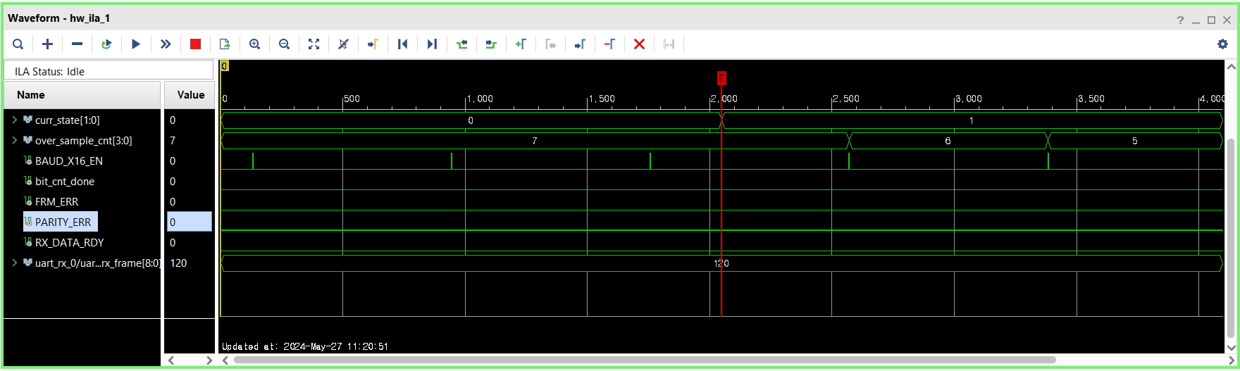
- 에러 수정 과정 및 디버깅
- 정상 작동 영상
[ 수정된 uart_rx_cntl.v 전체 코드 ]
`timescale 1ns / 1ps
//////////////////////////////////////////////////////////////////////////////////
// Company:
// Engineer:
//
// Create Date: 2024/05/20 10:15:18
// Design Name:
// Module Name: uart_rx_cntl
// Project Name:
// Target Devices:
// Tool Versions:
// Description:
//
// Dependencies:
//
// Revision:
// Revision 0.01 - File Created
// Additional Comments:
//
//////////////////////////////////////////////////////////////////////////////////


module uart_rx_cntl(
    input RST,
    input CLK,
(* mark_debug = "true" *)
    input RXD,
(* mark_debug = "true" *)
    input BAUD_X16_EN,  //over_sample_cnt_done,
    output [7:0]    RX_DATA,
(* mark_debug = "true" *)
    output reg             RX_DATA_RDY,
(* mark_debug = "true" *)
    output  reg     FRM_ERR,
(* mark_debug = "true" *)
    output                  PARITY_ERR
//    output reg [1:0] fsm_state
    );

localparam [1:0]    idle = 2'b00,
                    start = 2'b01,
                    data  = 2'b10,
                    stop = 2'b11;
(* mark_debug = "true" *)
reg [1:0]   curr_state;//
reg [1:0]  next_state;
(* mark_debug = "true" *)
wire        over_sample_cnt_done;
(* mark_debug = "true" *)
reg [3:0]   over_sample_cnt;
(* mark_debug = "true" *)
reg [3:0]   bit_cnt;
(* mark_debug = "true" *)
wire        bit_cnt_done;
(* mark_debug = "true" *)
reg [8:0]   rx_frame;

reg rx_d;

always @(posedge CLK)
begin
    if(RST)
        curr_state <= idle;
    else
        curr_state <= next_state;
end  //always

always @(curr_state, over_sample_cnt_done, bit_cnt_done, RXD)
begin
    case (curr_state)
        idle : begin
            if(RXD == 1'b0)
                next_state = start;
            else
                next_state = idle;
//            fsm_state = 2'b00;
        end
        start : begin
            if(over_sample_cnt_done) begin
                if(RXD)
                    next_state = idle;
                else
                    next_state = data;
            end else begin
                next_state = start;
            end
//            fsm_state = 2'b01;
        end
        data : begin
            if(over_sample_cnt_done && bit_cnt_done)
                next_state = stop;
            else
                next_state = data;
//            fsm_state = 2'b10;
        end
        stop : begin
            if(over_sample_cnt_done)
                next_state = idle;
            else
                next_state = stop;
//            fsm_state = 2'b11;
        end
        default : next_state = idle;
    endcase
end //always

// over sample count
always @(posedge CLK)
begin
    if(RST || curr_state == idle)
        over_sample_cnt <= 4'd7;
    else if (BAUD_X16_EN) begin
        if(over_sample_cnt_done)
            over_sample_cnt <= 4'd15;
        else
            over_sample_cnt <= over_sample_cnt - 1;
    end
end
assign over_sample_cnt_done = (over_sample_cnt == 4'd0) & BAUD_X16_EN;

// bit cnt generate
always @(posedge CLK)
begin
    if(RST || curr_state != data)
        bit_cnt <= 4'd0;
    else if(over_sample_cnt_done)
        bit_cnt <= bit_cnt + 1;
end //always
assign bit_cnt_done = (over_sample_cnt_done && (bit_cnt == 4'd8));


// output data generate
assign RX_DATA = rx_frame[7:0];

always @(posedge CLK)
begin
    if (RST)
        rx_frame <= 9'd0;
     else if (curr_state == data && over_sample_cnt_done)
        rx_frame[bit_cnt] <= RXD;
end  //always

//always @(posedge CLK)
//    rx_d <= RXD;

 always @(posedge CLK)
    RX_DATA_RDY <= bit_cnt_done;

assign PARITY_ERR = RX_DATA_RDY & ( rx_frame[8] != ^RX_DATA);

always @(posedge CLK)
begin
    if(RST)
        FRM_ERR <= 1'b0;
    else if((curr_state == stop) && over_sample_cnt_done)
        if (!RXD)
            FRM_ERR <= 1'b1;
        else
            FRM_ERR <= 1'b0;
end

endmodule
- UART RX Schematic

실습 2: 메모리(RAM) 설계
- ROM(Read Only Memory): 한 번 기록된 정보가 전원과 무관하게 반영구적으로 기억되는 삭제나 수정이 불가능한 기억장치
- RAM(Random Access Memory): 사용자가 자유롭게 데이터를 읽고, 쓰고, 지울 수 있는 기억장치
- 아래 코드에서는 두 개의 ROM이 존재(NUM_10S에서와 NUM_1S에서)
always @(CA, NUM_1S, NUM_10S)
begin
    if (CA) begin
        case (NUM_10S)
            4'd0 : AN = 7'h7e;
            4'd1 : AN = 7'h30;
            4'd2 : AN = 7'h6d;
            4'd3 : AN = 7'h79;
            4'd4 : AN = 7'h33;
            4'd5 : AN = 7'h5b;
            4'd6 : AN = 7'h5f;
            4'd7 : AN = 7'h70;
            4'd8 : AN = 7'h7f;
            4'd9 : AN = 7'h7b;
            default : AN = 7'h00;
        endcase
    end else begin
        case (NUM_1S)
            4'd0 : AN = 8'h7e;
            4'd1 : AN = 8'h30;
            4'd2 : AN = 8'h6d;
            4'd3 : AN = 8'h79;
            4'd4 : AN = 7'h33;
            4'd5 : AN = 7'h5b;
            4'd6 : AN = 7'h5f;
            4'd7 : AN = 7'h70;
            4'd8 : AN = 7'h7f;
            4'd9 : AN = 7'h7b;
            default : AN = 8'h00;
        endcase
    end
end
- FIFO(First Input First Output): 선입선처리에 따라 순서대로 데이터를 처리하는 형식
[ RAM 설계 참고사항 ]
- PORT
- RST
- CLK
- DIN [7:0]
- DOUT [7:0]
- RW (1: READ, 0: WRITE)
- ADDR [3:0] (Address) -> 총 4비트이므로 Address가 0~15까지
- 위의 Address 선언에 맞게 메모리 구성 -> reg [7:0] mem[0:15]
- Read: mem[ADDR] = DIN
- Write: DOUT = mem[ADDR]
1. my_ram 프로젝트 만들기
2. Add Source로 my_ram.v 생성 후 I/O 포트 정의
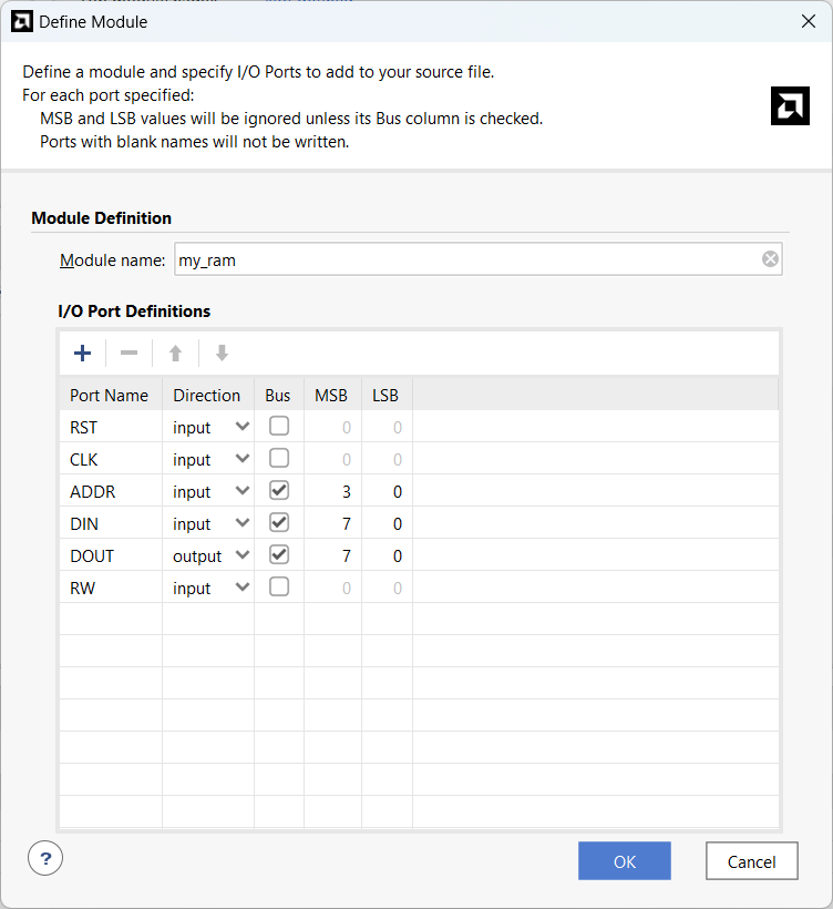
3. 메모리를 생성하기 위해 위의 참고사항을 이용해 reg 선언
reg [7:0] mem [0:15];
4. CLK의 Rising Edge마다 Read를 기본으로 실행하기 위해(Reset이 0이 아닐 때) 코드 작성
always @(posedge CLK) //read 부분
begin
    if(RST)
        DOUT <= 8'd0;
    else
        DOUT <= mem [ADDR]; //RST이 0이 아니라면 기본으로 Read를 실행
end
5. RW 모드가 0이면 Write 실행하기 위한 코드 작성
always @(posedge CLK)
begin
    if(RW == 1'b0)  //RW의 모드가 0이므로 Write 실행
        mem[ADDR] <= DIN;
end
6. 위와 같이 코드를 작성할 경우, ADDR이 Read와 Write 모드에서 동일할 때 출력되는 값(Read되는 값)이 기존의 Data일 수도 있고, 새롭게 Write된 값일 수 있으므로 이를 지정하기 위해 Write First로 진행하여 방지 가능
- 또는 Read_addr와 Write_addr를 분리하여 위와 같은 오류를 방지할 수 있음
7. Simulation 돌려보기 위해 testbench 파일을 만들고 검증하기
7-1. my_ram 모듈을 인스턴스화하기 위해 코드 작성 후 포트 맵핑
my_ram uut(
    .RST    (rst),
    .CLK    (clk),
    .ADDR   (addr),
    .DIN    (din),
    .DOUT   (dout),
    .RW     (rw)
    );
인스턴스화(Instantiation)란?
다른 파일에서 선언한 모듈을 가져올 때 사용하는 방법.
위 코드에서는 my_ram.v 파일에서 선언한 my_ram이라는 모듈을 my_ram_tb.v파일로 가져오기 위해 사용함.
[선언 형식]
가져올 module 이름 module 이름 선언 (
.가져올 module의 port1 (연결할 현재 module의 port1),
.가져올 module의 port2 (연결할 현재 module의 port2),
.가져올 module의 port3 (연결할 현재 module의 port3),
....
....
);
7-2. 아래에서 사용할 i를 integer로 선언 후 시뮬레이션 코드 작성
[ 전체 코드 ]
`timescale 1ns / 1ps

module my_ram_tb();
parameter CLK_PD = 8.0;
reg rst, clk, rw;
reg [3:0] addr;
reg [7:0] din;
wire [7:0] dout;

integer i;

my_ram uut(
    .RST    (rst),
    .CLK    (clk),
    .ADDR   (addr),
    .DIN    (din),
    .DOUT   (dout),
    .RW     (rw)
    );

initial begin   //testbench 코드 작성할 때 초기에 rst을 ON/OFF 해주고 시작하는 부분
    rst = 1'b1;
    #(CLK_PD*10);
    rst = 1'b0;
end

initial clk = 1'b0;
always #(CLK_PD/2) clk = ~clk;  //clk를 0에서 시작하여 CLK_PD를 주기로 1, 0을 반복하도록 신호를 만드는 코드

initial begin
    addr = 4'd0;
    din = 8'd0;
    rw = 1'b1;  //이 세 줄은 초기조건 설정
    wait (rst == 1'b0);
    #(CLK_PD*20);
    rw = 1'b0;  //wirte 모드 시작
    for (i = 0; i < 16; i = i+1) begin //memory의 addr공간이 0~15까지 존재하므로 각 주소에 0~15까지 입력
        addr = i;
        din = i;
        #(CLK_PD);
    end
    #(CLK_PD*20);
    rw = 1'b1;  //read 모드 시작
    for (i = 0; i < 16; i = i+1) begin //memory의 addr공간이 0~15까지 존재하므로 각 주소0~15까지의 Data를 불러오기
        addr = i;
        #(CLK_PD);
    end

    #1000;
    $finish;
end
endmodule
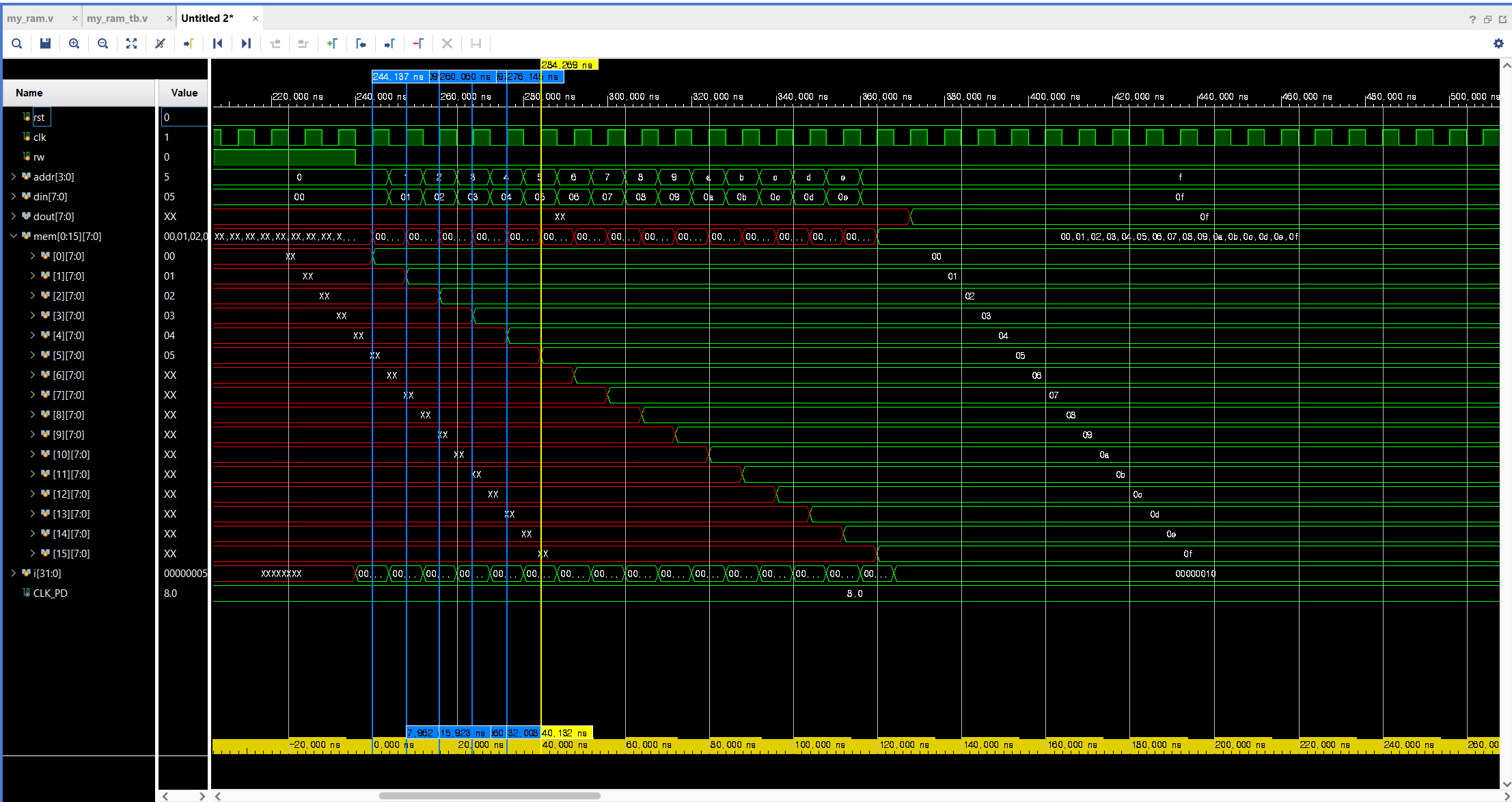
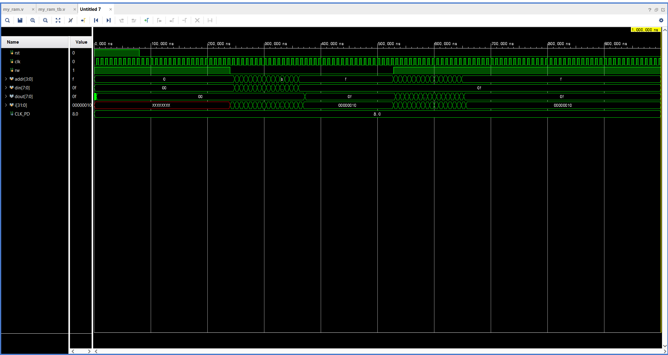
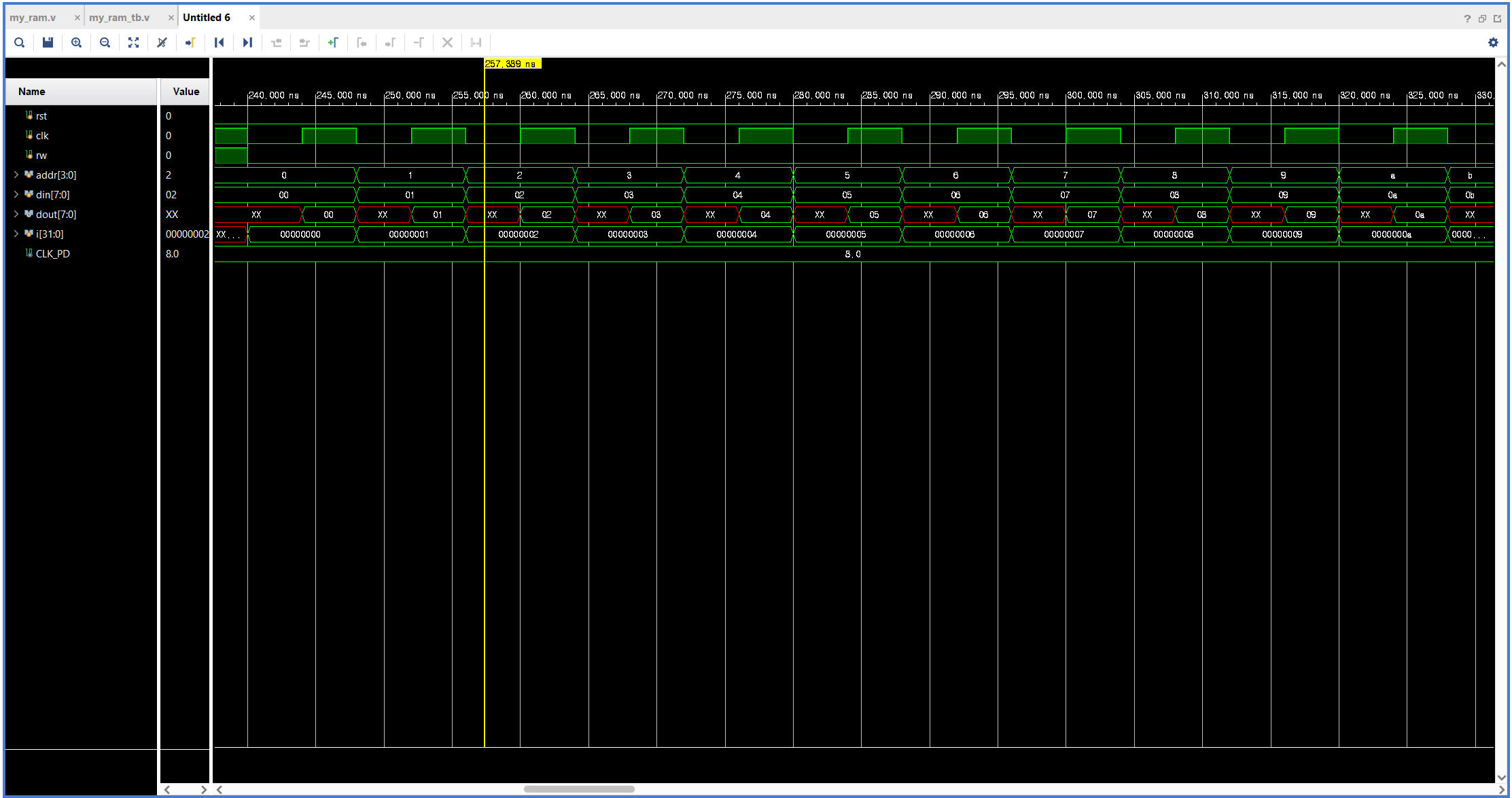
7-3. 시뮬레이션 결과: 각 Address에 Write하는 과정(위)과 Address에서 Read하는 과정(아래)

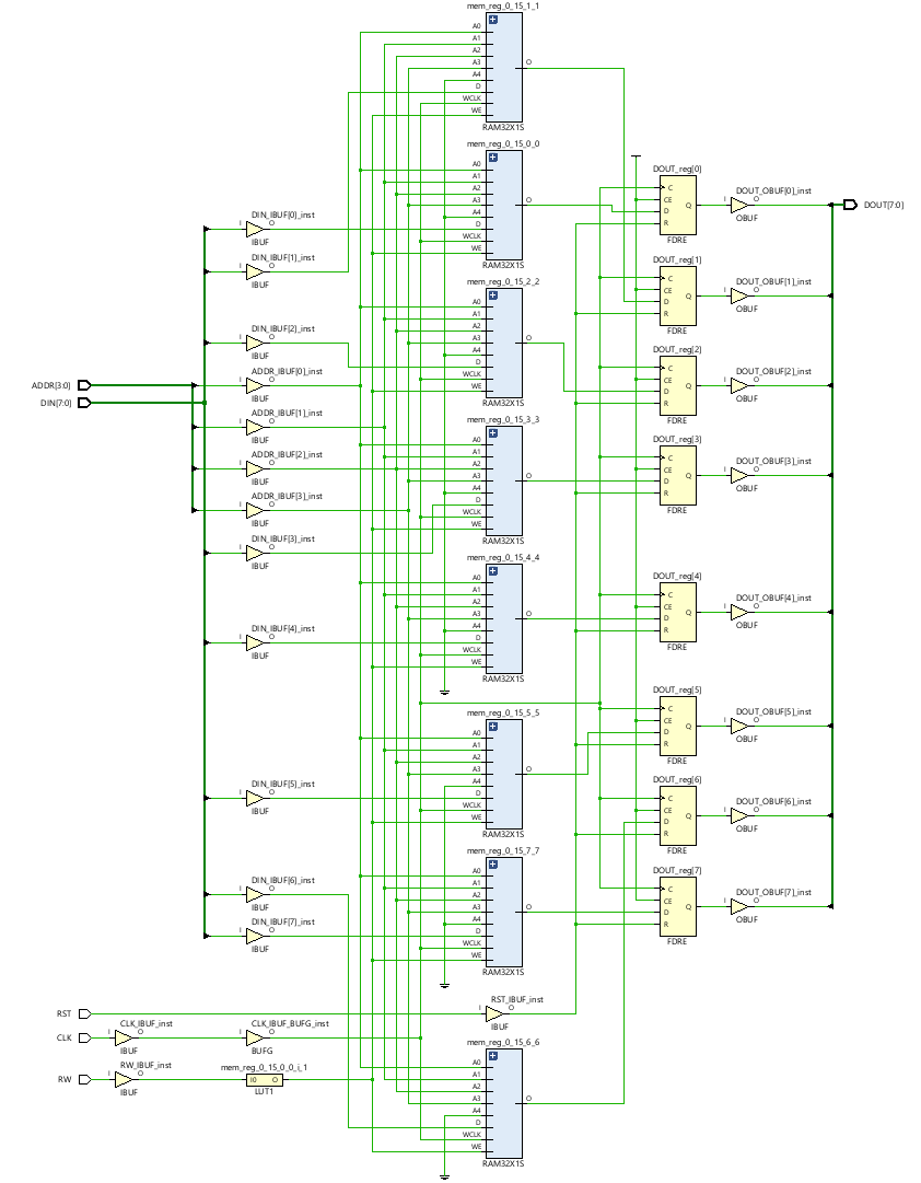
- 위 RAM의 Schematic
8. 위 Simulation 결과중 dout이 wirte모드에서 Unknown이 되지 않도록 하기 위해 -> memory의 초기값을 0으로 설정
memory 생성을 위해 mem을 reg로 선언한 코드를 다음과 같이 변경: (2차원 verilog 배열 초기화)
reg [7:0] mem [0:15] = {default:0};
9. always @(posedge CLK)구문은 Synchronous, assign구문은 Asynchronous이므로 assign으로 변경해보기(my_ram.v파일 수정)
module my_ram(
    input RST,
    input CLK,
    input [3:0] ADDR,
    input [7:0] DIN,
    output [7:0] DOUT,
    input RW
    );

//reg [7:0] mem [0:15];  //메모리를 생성하기 위해 reg 사용 reg [7:0]은 데이터 크기의 맞춤. [0:15]는 ADDR이 4비트이므로 0~15로 선언
reg [7:0] mem [0:15]; //선언한 memory 0으로 초기화하기

assign DOUT = mem[ADDR];
/**********
always @(posedge CLK) //read 부분
begin
    if(RST)
        DOUT <= 8'd0;
    else
        DOUT <= mem [ADDR]; //RST이 0이 아니라면 기본으로 Read를 실행
end
***********/

always @(posedge CLK)
begin
    if(RW == 1'b0) //RW의 모드가 0이므로 Write 실행
        mem[ADDR] <= DIN;

end
endmodule
10. testbench 결과: always구문을 사용했을 때와 다르게 din 값이 즉각적으로 변함
'하만(Harman) 세미콘 반도체 설계 과정 > Verilog를 이용한 RTL 시스템 반도체 설계' 카테고리의 다른 글
| 하만(Harman) 세미콘 아카데미 61일차 - Verilog HDL 설계(UART_TX 설계) (0) | 2024.06.10 |
|---|---|
| 하만(Harman) 세미콘 아카데미 57일차 - Verilog HDL 설계(FIFO 설계, 테스트벤치 코드 작성방법) (2) | 2024.06.03 |
| 하만(Harman) 세미콘 아카데미 47일차 - Verilog HDL 설계(UART 실습) (0) | 2024.05.20 |
| 하만(Harman) 세미콘 아카데미 46일차 - Verilog HDL 설계(Serial to Parallel, Parallel to Serial 변환) (0) | 2024.05.17 |